

Common Wear Patterns
Carbide drawing dies do not always wear uniformly. Different wear patterns provide information about the drawing process.
|
Wear Pattern |
Possible Process Issue |
|
Uniform bearing enlargement |
Normal progressive wear |
|
One-sided bearing wear |
Die or wire misalignment |
|
Localized groove |
Abrasive contamination |
|
Entry-edge damage |
Improper threading or wire impact |
|
Surface scoring |
Damaged bearing or contaminated lubricant |
|
Rapid bore enlargement |
Excessive load or unsuitable carbide grade |
Die Geometry
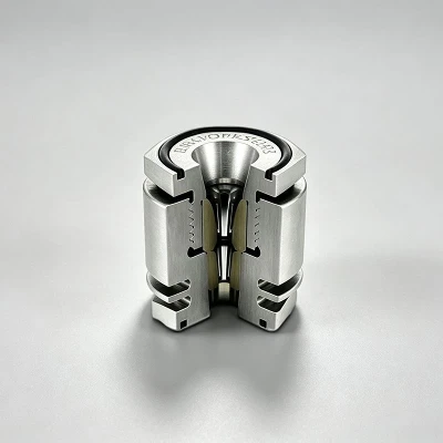
The internal geometry of a Carbide Wire Drawing Die determines how the wire enters, deforms, and exits the tool.
The main sections are:
Approach zone
Guides and receives the incoming wire.
Reduction zone
Applies the primary cross-sectional deformation.
Bearing
Controls the final diameter.
Exit zone
Provides a controlled transition as the wire leaves the die.
The bearing is normally the most closely monitored section because wear in this area changes the effective die opening and can directly affect finished-wire diameter.
Reduction Ratio and Die Selection
Die selection should be based on cross-sectional area reduction, rather than simply comparing inlet and outlet diameters.
For example, when wire diameter changes from 3.00 mm to 2.60 mm:
The appropriate reduction depends on the wire material and drawing process. Steel wire, copper wire, aluminum wire, and brass wire have different deformation characteristics, so the same reduction percentage should not automatically be applied to every material.
Application by Wire Material
Carbide Wire Drawing Dies can be configured for different materials, including carbon steel, stainless steel, copper, aluminum, brass, and other metal wires.
For harder steel or stainless steel wire, die selection needs to consider the higher drawing load and potential abrasive wear. For softer copper or aluminum wire, the focus may shift toward bearing surface finish, lubrication, dimensional stability, and prevention of surface scratches.
The die geometry and carbide grade should therefore be selected according to the actual wire grade rather than using one specification for all materials.
Drawing Process Integration
A typical carbide-die drawing line can be arranged as:
Wire Rod → Surface Preparation → Descaling / Cleaning → Lubrication → Drawing Die → Capstan → Intermediate Die → Cooling / Lubrication → Final Drawing → Diameter Inspection → Take-Up
In a multi-die machine, each die is positioned according to the required reduction sequence. The wire speed increases as its diameter decreases, so the drawing system must maintain appropriate synchronization between capstans and dies.
Working Conditions
During operation, the die is exposed to wire-die contact pressure, tensile drawing force, friction, and heat generated by deformation and sliding.
Important process variables include:
Wire diameter
Reduction per pass
Drawing speed
Drawing tension
Lubricant temperature
Lubricant flow
Wire hardness
Die alignment
If the reduction is excessive or lubrication is insufficient, drawing force and frictional heat can increase. This can accelerate bearing wear and cause dimensional instability.

Surface Finish and Wire Quality
The surface condition of the die bearing has a direct effect on the surface of the drawn wire. A damaged or contaminated bearing can generate longitudinal scratches, scoring, or irregular surface marks.
For applications involving copper or aluminum wire, the drawing system should maintain clean lubrication because relatively soft wire can reproduce small defects from the die surface. During maintenance, the die bore should therefore be inspected together with the incoming wire and lubricant filtration system.
Carbide Die Selection for Replacement
When replacing an existing die, using the previous nominal diameter alone may result in an unsuitable replacement. Engineers should compare the actual incoming diameter, actual finished diameter, production tolerance, reduction per pass, and previous die wear pattern.
For example, if the previous die produced a target diameter of 1.20 mm but the actual output gradually increased to 1.23 mm, the replacement should not automatically be specified as another 1.20 mm die. The engineer should first determine whether the increase was caused by normal bearing wear, excessive reduction, alignment, or an incorrect original specification.
FAQ
Q: How do I select the correct Carbide Wire Drawing Die for each drawing pass?
A: The die should be selected according to the incoming wire diameter, target outlet diameter, wire material, reduction per pass, drawing speed, lubrication, and required tolerance. In a multi-pass line, each die should be matched to its specific reduction stage rather than selected only according to the final wire diameter.
Q: What information is required to order Carbide Wire Drawing Dies?
A: For an accurate quotation, provide the wire material, inlet diameter, outlet diameter, diameter tolerance, reduction per pass, drawing speed, lubrication method, die-holder dimensions, and machine type. If replacing an existing die, production data such as actual wire diameter and previous die life can also help determine the specification.
Q: What causes the finished wire diameter to increase during production?
A: A gradual increase in finished diameter is commonly associated with bearing wear, because continuous wire contact enlarges the effective die opening. Other possible causes include excessive drawing load, unsuitable die geometry, misalignment, or changes in incoming wire diameter. Measuring both the die bore and finished wire can help identify the actual cause.
Q: What causes uneven wear in a Carbide Wire Drawing Die?
A: Uneven or one-sided bearing wear is often related to misalignment between the die and wire centerline. Incorrect die seating, an off-center wire guide, excessive drawing tension, or uneven incoming wire conditions can concentrate contact on one side of the bearing.
Hot Tags: carbide wire drawing dies, China carbide wire drawing dies manufacturers, suppliers, factory