
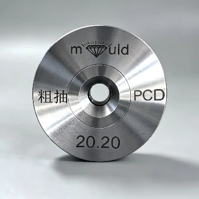
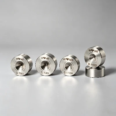
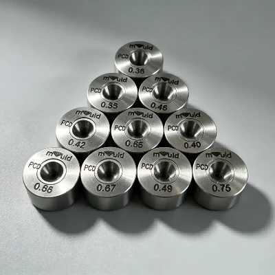
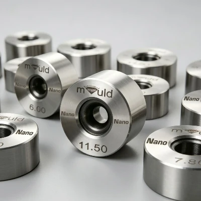
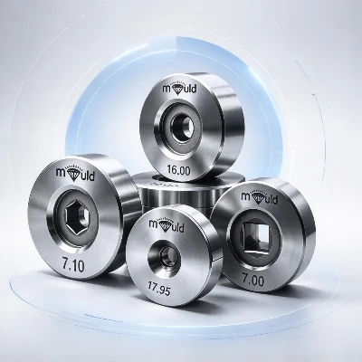
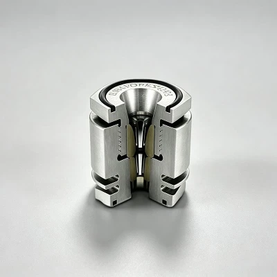
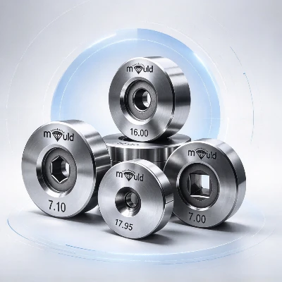
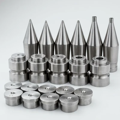
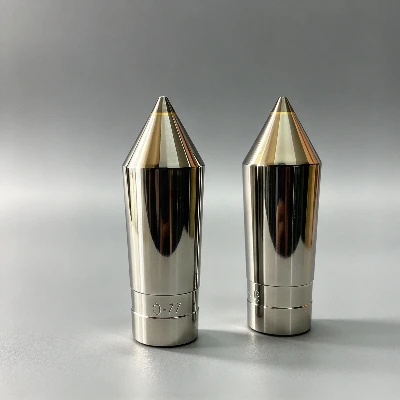
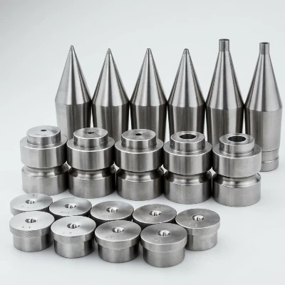
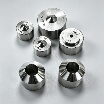
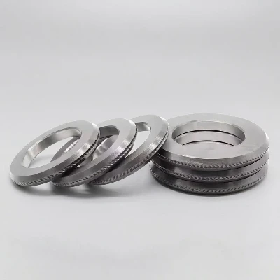
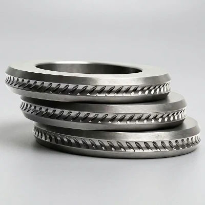
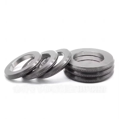
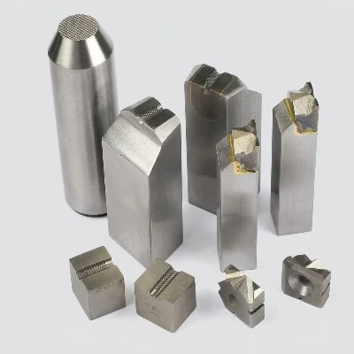
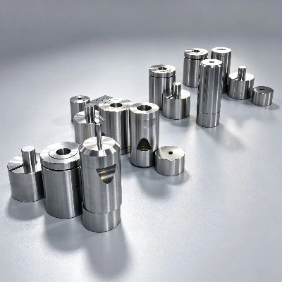

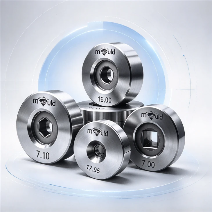
Die Structure
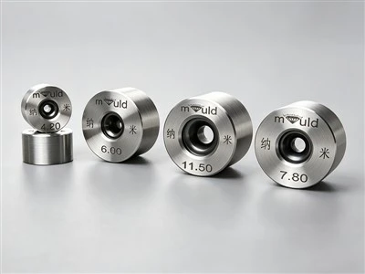
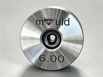
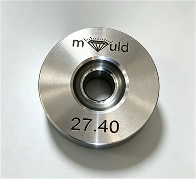
A typical Carbide Die for Wire Drawing consists of four functional sections:
Entry zone - receives and guides the incoming wire.
Reduction zone - progressively compresses the wire.
Bearing - controls the final wire diameter.
Exit zone - guides the drawn wire away from the sizing section.
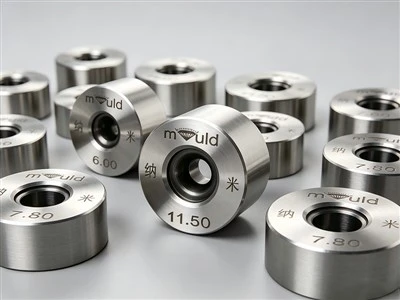
The carbide insert provides the working surface, while the external holder supports the insert and maintains its position inside the drawing machine.
Carbide Material
The working insert is generally made from cemented tungsten carbide, consisting of tungsten carbide particles bonded with a metallic binder, commonly cobalt.
The carbide composition affects the balance between hardness, wear resistance, fracture resistance, and toughness. Therefore, the appropriate grade depends on the wire material and drawing conditions rather than simply selecting the hardest available carbide.
Application by Wire Material
Carbide drawing dies can be configured for different materials, including:
Carbon steel wire
Stainless steel wire
Copper wire
Aluminum wire
Brass wire
Alloy wire
Hard steel and stainless steel generally place greater mechanical and abrasive loads on the die, while copper and aluminum applications often place greater emphasis on bearing finish, lubrication, and surface quality.

Drawing Process
A typical production process is:
Wire Rod → Surface Preparation → Lubrication → Carbide Die → Drawing Block → Intermediate Die → Lubrication/Cooling → Final Die → Diameter Inspection → Take-Up
In a multi-pass machine, the wire velocity increases as its cross-sectional area decreases. The drawing machine therefore needs to coordinate the die sequence and capstan speeds to maintain stable wire tension.
Die Geometry
The internal geometry directly affects deformation and drawing load. Important parameters include:
Approach angle
Reduction zone length
Bearing length
Exit geometry
Bore diameter
Bore roundness
Surface finish
The bearing is particularly important because it determines the final sizing condition. Excessive bearing length can increase contact and friction, while insufficient bearing length may reduce dimensional control.
Working Conditions
During drawing, the die is exposed to compressive contact pressure, wire tension, sliding friction, and heat generated by deformation and friction.
The actual operating condition depends on:
Wire material and hardness
Reduction per pass
Drawing speed
Lubrication
Die geometry
Machine alignment
Increasing drawing speed or reduction without sufficient lubrication can increase drawing force and frictional temperature, accelerating die wear.
Die Alignment
The carbide die must remain concentric with the wire path. Incorrect alignment can concentrate contact on one side of the bearing and cause uneven wear.
During installation, engineers should check:
Wire Guide → Die Holder → Die Bore → Drawing Block
All should maintain the correct centerline. A misaligned die may produce wire ovality even when the nominal bore diameter is correct.
FAQ
Q: How do I choose the right carbide grade?
A: Carbide grade selection should consider wire hardness, tensile strength, reduction per pass, drawing speed, abrasive conditions, and impact risk. Wear resistance should not be considered separately from toughness because a die exposed to mechanical impact may require a different carbide composition from one operating under stable continuous drawing.
Q: What causes scratches on wire drawn through a carbide die?
A: Possible causes include scratched or damaged bearing surfaces, contaminated lubricant, abrasive particles, poor die alignment, and defects on the incoming wire. The die bore, lubrication system, and incoming wire should be inspected before changing the drawing parameters.
Q: Can Carbide Drawing Dies be used for different wire materials?
A: Yes, carbide dies can be designed for carbon steel, stainless steel, copper, aluminum, brass, and other metal wires. However, the same die specification should not automatically be transferred between materials because wire hardness, drawing force, lubrication requirements, and allowable reduction can differ significantly.
Q: Can the dies be customized for an existing drawing machine?
A: Yes. Customization can cover the bore diameter, bearing length, reduction geometry, carbide grade, external dimensions, and holder configuration. The machine model, die-holder dimensions, wire path, and current drawing schedule should be provided to ensure correct mechanical integration.
Hot Tags: carbide dies for wire drawing, China carbide dies for wire drawing manufacturers, suppliers, factory