

Procurement Specification
|
Parameter |
Required Data |
|
Wire Material |
Steel / Stainless Steel / Copper / Aluminum / Brass |
|
Wire Grade |
Specific material grade |
|
Inlet Diameter |
Diameter before drawing |
|
Outlet Diameter |
Target diameter |
|
Reduction per Pass |
Cross-sectional reduction |
|
Drawing Speed |
Actual operating speed |
|
Lubrication |
Dry / Oil / Water-based |
|
Carbide Grade |
Required or recommended |
|
Die Geometry |
Approach and bearing requirements |
|
Holder |
Mounting dimensions |
|
Machine |
Drawing machine configuration |
|
Tolerance |
Finished-wire dimensional requirement |
Material and Construction
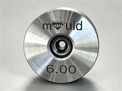
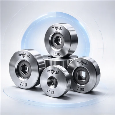
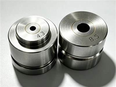
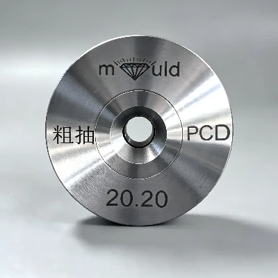
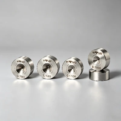
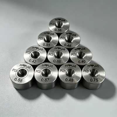
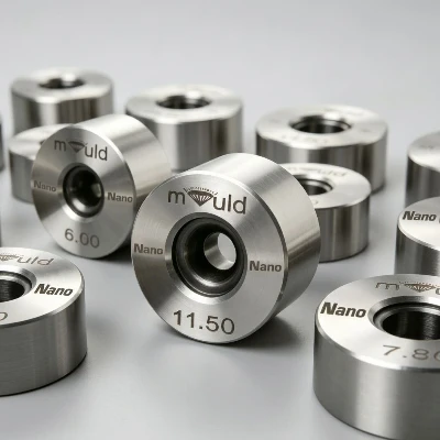
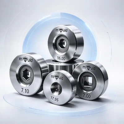
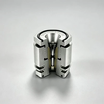
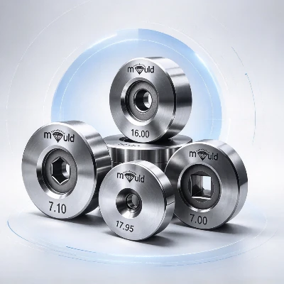
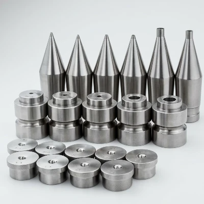
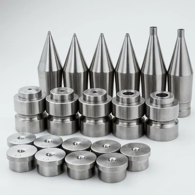
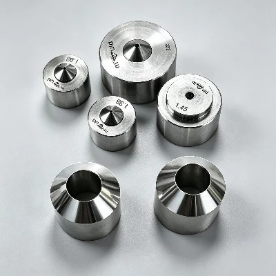
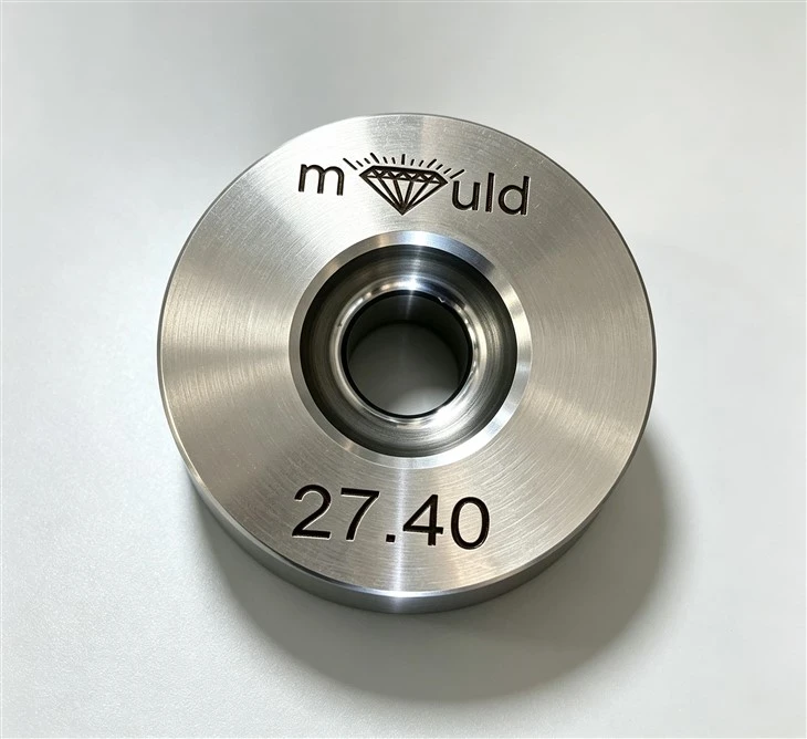
A cemented carbide die is manufactured from tungsten carbide particles bonded with a metallic binder, commonly cobalt. The carbide insert is precision-machined and finished to form the internal drawing profile, then mounted in a supporting steel holder when required.
The internal profile normally contains an entry section, approach/reduction zone, bearing, and exit section. The bearing controls the final wire diameter, while the approach zone determines how the wire is progressively compressed before reaching the sizing section.
Engineering Application
The main purpose of the die is to provide a controlled reduction path while maintaining stable wire dimensions over repeated drawing passes. For example, a drawing line may process:
4.50 mm → 4.00 mm → 3.55 mm → 3.15 mm → 2.80 mm
Each die is responsible for one reduction stage, allowing the total deformation to be distributed across the machine rather than concentrated in a single die.
This approach is particularly important for steel and other materials where excessive reduction in one pass can significantly increase drawing force and heat generation.
Die Geometry and Wire Deformation
The geometry of the carbide die determines how the wire changes shape as it passes through the tool. The approach angle controls the initial deformation zone, while the bearing establishes the final cross-sectional dimension.
For procurement, bearing length should be considered together with wire diameter, material hardness, reduction per pass, and drawing speed. An inappropriate bearing length can increase contact area and friction or provide insufficient sizing control.
Carbide Grade Selection
Different cemented carbide grades provide different combinations of hardness, toughness, fracture resistance, and wear resistance. Grade selection should therefore be based on the actual drawing load and wear mechanism.
For example, a drawing process involving hard steel wire and abrasive surface contamination may place greater emphasis on wear resistance, while an application exposed to mechanical impact or unstable threading may require greater toughness.
The carbide grade should be specified together with the wire material, hardness, reduction ratio, and operating conditions, rather than selected independently.
Suitable Wire Materials
Cemented Carbide Drawing Dies can be used for a range of metal wires, including:
Carbon steel wire
Stainless steel wire
Copper wire
Aluminum wire
Brass wire
Alloy wire
The same die geometry should not automatically be applied to different materials. Steel and stainless steel generally generate different drawing loads from copper or aluminum, so the carbide grade, reduction schedule, lubrication, and bearing geometry may need to be changed accordingly.

Operating Conditions
During continuous drawing, the carbide bearing is subjected to compressive contact loading, wire tension, sliding friction, and deformation-related heat.
The actual operating condition is determined by factors such as wire diameter, reduction per pass, drawing speed, material hardness, die angle, and lubricant condition. Increasing speed or reduction without adequate lubrication can increase drawing force and interface temperature.
For production monitoring, engineers should record drawing tension, speed, lubricant temperature, lubricant flow, finished diameter, and wire surface condition.
Wear and Failure Modes
The most common failure mechanism is progressive bearing wear, which increases the effective die opening and causes the finished wire diameter to drift upward.
Other observable failures include:
|
Failure |
Typical Observation |
|
Bearing wear |
Increasing finished-wire diameter |
|
Uneven wear |
Increased wire ovality |
|
Surface damage |
Longitudinal wire scratches |
|
Edge chipping |
Local damage near entry or exit |
|
Carbide cracking |
Sudden dimensional or surface defects |
|
Thermal damage |
Accelerated wear under high-speed drawing |
Integration into a Drawing Line
Cemented Carbide Drawing Dies are normally installed inside a die box, die cassette, or individual die holder.
A typical production sequence is:
Wire Preparation → Lubrication → Carbide Drawing Die → Drawing Block → Intermediate Die → Cooling/Lubrication → Final Drawing → Diameter Inspection → Take-Up
In multi-pass equipment, the die sequence must be synchronized with the drawing blocks because the wire velocity increases as its cross-sectional area decreases.
Inspection and Process Control
Inspection should cover both the die and the finished wire. Important die parameters include bore diameter, bearing length, bore roundness, surface condition, concentricity, and carbide integrity.
On the production side, engineers should monitor wire diameter, ovality, surface defects, drawing tension, and production length per die. Comparing these measurements makes it possible to distinguish normal die wear from problems caused by machine alignment or lubrication.
FAQ
Q: What cemented carbide grade should be used for wire drawing dies?
A: The carbide grade should be selected according to wire material, hardness, reduction per pass, drawing speed, and expected wear mechanism. Harder grades can be considered for abrasive drawing conditions, while grades with higher toughness may be more appropriate where impact or unstable threading is present.
Q: What is the difference between cemented carbide and conventional steel drawing dies?
A: Cemented carbide provides a harder and more wear-resistant working surface than conventional tool steel. This makes it suitable for continuous wire contact where the die must maintain its bore diameter, bearing geometry, and surface condition over repeated drawing passes.
Q: How does the carbide binder content affect die performance?
A: The metallic binder content influences the balance between hardness and toughness of the cemented carbide. A lower binder content generally favors higher hardness and wear resistance, while a higher binder content can provide greater toughness. The appropriate composition depends on wire hardness, drawing load, and impact conditions.
Q: How do I know whether the carbide die grade is suitable for my wire?
A: Compare the die grade with the actual wire material, tensile strength, hardness, reduction per pass, drawing speed, and previous die failure mode. If a die shows rapid abrasive wear, a more wear-resistant grade may need evaluation; if cracking or chipping occurs, toughness and installation conditions should be investigated.
Q: What causes cracking or chipping of a cemented carbide drawing die?
A: Cracking or chipping can result from mechanical impact during threading, excessive drawing load, improper die seating, misalignment, insufficient holder support, or a carbide grade with insufficient toughness. Installation damage should be distinguished from normal bearing wear because the corrective action is different.
Hot Tags: cemented carbide drawing dies, China cemented carbide drawing dies manufacturers, suppliers, factory