

Procurement Specification
|
Parameter |
Required Data |
|
Wire Material |
Copper / Aluminum / Steel / Other |
|
Incoming Shape |
Round / Existing Profile |
|
Incoming Size |
Diameter or W × T |
|
Finished Profile |
Square / Rectangular / Flat / Custom |
|
Finished Dimensions |
Width × Thickness |
|
Corner Radius |
Required value |
|
Profile Tolerance |
± value |
|
Reduction per Pass |
Area reduction |
|
Drawing Speed |
Actual machine speed |
|
Lubrication |
Wet / Dry |
|
PCD Grade |
Grain size / blank type if specified |
|
Holder |
External dimensions |
|
Machine |
Drawing machine model |
|
Production Requirement |
Meters per die / batch quantity |
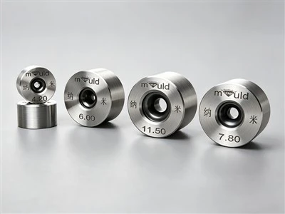
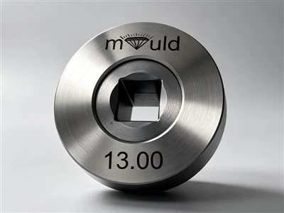
A round drawing die produces a circular wire. When the required product has a rectangular, square, triangular, hexagonal or other profile, the drawing process needs a shaped die with a corresponding internal profile.
The die therefore performs two operations simultaneously:
Reduces the cross-sectional area of the incoming wire
Transforms the wire into the required cross-sectional geometry
For example:
Round copper wire → Intermediate reduction → PCD shaped die → Rectangular copper wire → Final sizing
This approach is used when the final conductor geometry must be controlled directly during drawing rather than machining or mechanically reshaping the wire after drawing.
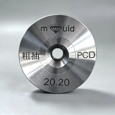
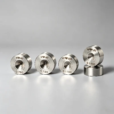
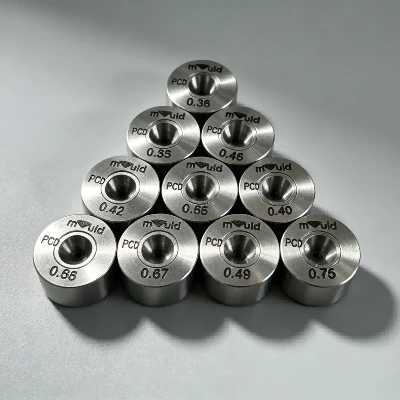
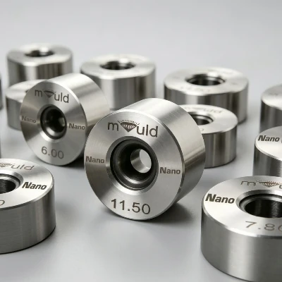
PCD Working Element
The working insert is manufactured from polycrystalline diamond, which consists of randomly oriented diamond particles consolidated into a polycrystalline structure. Commercial PCD drawing dies are available with different diamond grain sizes; published specifications include approximately 1, 3, 5, 10–12, 25 and 50 μm classes, with grain selection affecting the balance between surface finish and wear behavior.
The PCD element can be supplied as a self-supported blank or a carbide-supported configuration, depending on die design and application requirements.
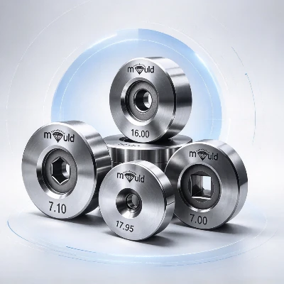
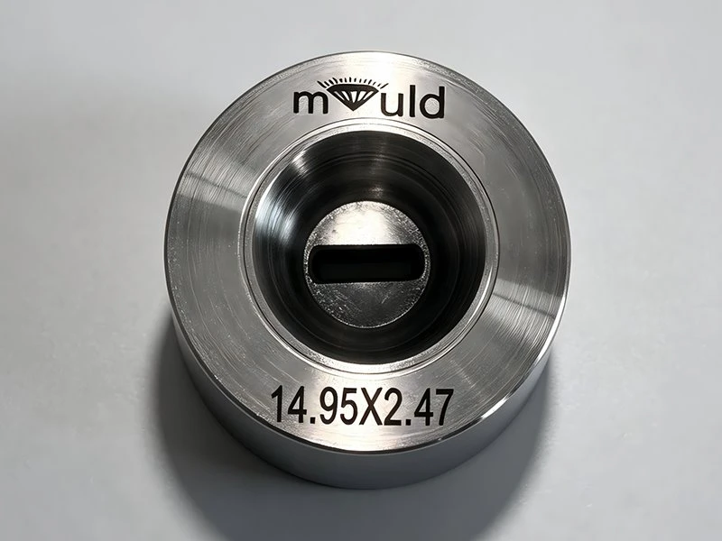
For a shaped die, the PCD working element is precision-machined to reproduce the required profile rather than a simple circular bore.
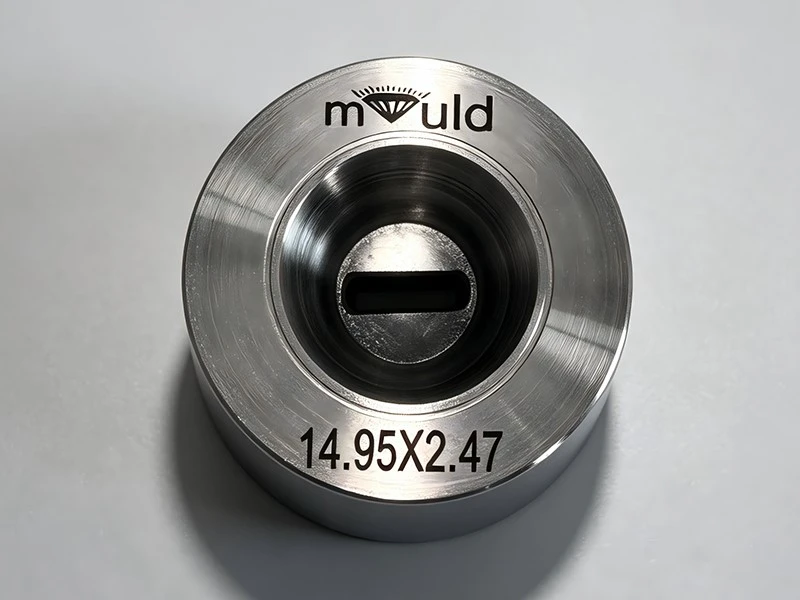
Shaped Die Geometry
The critical geometry includes:
Entry profile
Approach/reduction zone
Profile transition
Bearing or sizing section
Exit geometry
Corner radius or edge geometry
The bearing is particularly important because it determines the final cross-sectional dimensions. For shaped wire, dimensional control involves more than overall width and height; engineers may also need to control corner radius, diagonal dimension, flatness and profile symmetry.
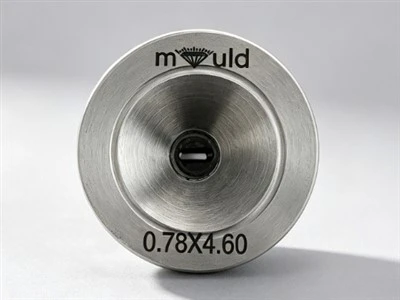
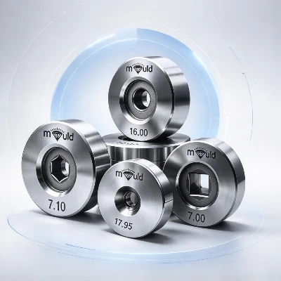
Available profiles can include square, rectangular, flat, triangular, hexagonal, oval, semicircular, rhombus and trolley-wire profiles. Customized profiles are also possible according to the final wire drawing.
Dimensional Range and Tolerance
The achievable size depends on the PCD blank, profile geometry, manufacturing process and required tolerance. Published shaped-die specifications show PCD profile dies starting from approximately 0.1 mm for some geometries, while other suppliers list specific minimum dimensions depending on the profile.
One published specification for shaped diamond dies lists examples such as:
Square hole: 0.18 × 0.18 mm
Flat square profile: 0.08 × 0.20 mm
Semicircular profile: 0.20 × 0.40 mm
Triangular profile: 0.25 × 0.25 mm
Profile tolerance: approximately ±0.001 mm for specified configurations
These values should be treated as reference manufacturing capabilities rather than universal limits, because the achievable tolerance depends on the profile size, corner geometry, PCD grade and inspection method.
Typical Wire Materials
PCD Shaped Wire Drawing Dies can be used for various non-ferrous and selected ferrous wires, depending on the PCD grade and drawing conditions. Common materials include:
Copper
Aluminum
Stainless steel
Tungsten
Molybdenum
Precious-metal wire
Special alloys
PCD drawing dies are also used for applications involving coated steel and other specialized wire materials.
Typical Application: Flat and Rectangular Copper Wire
One important application is rectangular or flat copper wire used in electrical equipment.
A typical process can be:
Copper rod → Rough drawing → Intermediate drawing → Profile forming → PCD Shaped Die → Final sizing → Dimensional inspection → Take-up
The shaped die is positioned at the appropriate stage after the round wire has been reduced to a diameter suitable for profile conversion.
The final wire is then checked for width, thickness, corner radius, profile symmetry, surface condition and cross-sectional area.
Drawing Speed and Thermal Conditions
During continuous drawing, the PCD profile is exposed to wire-die contact pressure, friction, drawing tension and heat generated by deformation and sliding.
For standard PCD blanks, one published specification gives a maximum recommended operating temperature of 650°C, while thermally stable PCD blanks are specified up to 850°C. These are material-specific limits, not recommended production temperatures; actual drawing temperature should normally remain controlled well below the material's maximum operating limit.
Drawing speed, lubricant supply and wire surface condition therefore need to be controlled together. Excessive friction can accelerate wear and alter the profile dimensions.
Lubrication
PCD Shaped Dies can be integrated into both wet and dry wire-drawing processes, depending on the wire material and machine configuration.
The lubricant performs several functions:
Reduces wire-die friction
Controls frictional heat
Removes particles from the working area
Reduces the risk of surface scratching
For fine shaped profiles, contamination is particularly important because particles trapped between the wire and profile surface can create localized scratches or alter the corner geometry.
System Integration
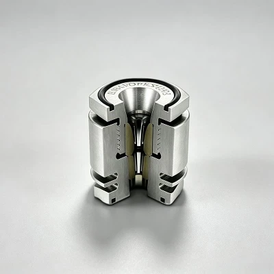
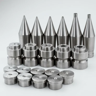
A PCD Shaped Wire Drawing Die is normally installed in a die box or shaped-die holder within the drawing machine.
A typical process is:
Wire Guide → Lubrication → Round Drawing → Profile Reduction → PCD Shaped Die → Cooling/Lubrication → Dimensional Inspection → Take-Up
The die centerline must match the incoming wire path. Incorrect alignment can create uneven contact around the profile and accelerate wear on one side or one corner.
For automated production, dimensional inspection can be placed downstream using laser diameter/profile measurement or other non-contact measurement equipment, depending on the wire geometry.
FAQ
Q: What causes the dimensions of a shaped wire to gradually change?
A: Progressive profile wear is one possible cause. Wear at the bearing can increase width or thickness, while localized wear can change the corner radius or produce an asymmetric profile. Incoming wire variation, excessive reduction, poor lubrication, and die misalignment should also be checked before replacing the die.
Q: How do I inspect a worn PCD Shaped Drawing Die?
A: Inspection should include the profile opening, width, thickness, corner geometry, surface condition, and symmetry of the working area. For production verification, compare these measurements with the finished wire's dimensions and the number of meters produced by the die.
Q: What causes corner wear in a PCD Shaped Wire Drawing Die?
A: Corner wear can result from uneven contact pressure, excessive local reduction, wire misalignment, abrasive contamination, or unsuitable lubrication. Because corners directly influence the final profile, even localized wear can change the finished wire geometry while the overall dimensions remain within tolerance.
Q: What drawing conditions should be considered when selecting a PCD Shaped Die?
A: The key conditions include wire material, incoming cross-section, reduction per pass, drawing speed, lubricant type and temperature, drawing tension, and machine alignment. These parameters determine the contact load and friction conditions acting on the PCD profile.
Q: Can the same PCD Shaped Die be used for different wire sizes?
A: Normally, a die should be designed for a specific incoming and finished profile. Changing the incoming size or reduction can alter the contact conditions and drawing load. If the production specification changes significantly, the die geometry should be reviewed rather than assuming the existing die is interchangeable.
Hot Tags: pcd shaped wire drawing dies, China pcd shaped wire drawing dies manufacturers, suppliers, factory