


Manufacturing Process
How We Manufacture Carbide Wire Drawing Dies
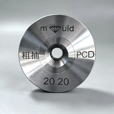
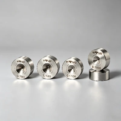
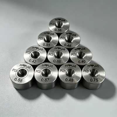
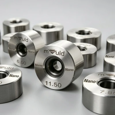
At Hejian Zhuying Carbide Dies Co., Ltd., carbide die manufacturing is a controlled process involving material selection, tooling preparation, precision machining, working-profile forming, grinding, polishing, dimensional inspection, and final verification.
For PCD Wire Drawing Dies, PCD Shaped Wire Drawing Dies, Extrusion Tips & Dies, Shaving Dies, Carbide Nail Dies, and Cold Heading Dies, the manufacturing process varies according to the tooling structure and application. The objective is not simply to produce a die with specified external dimensions-the working profile, dimensional accuracy, surface condition, carbide properties, and overall tooling structure must strictly correspond to the intended forming process.
Manufacturing Process at a Glance
Application and Drawing Review
Understanding Tooling Requirements Before Manufacturing
Before production, required die specifications and application conditions are reviewed. For customized tooling, customer inputs evaluated include:
For Shaped Dies, internal geometry dictates final wire profiles; for round dies, sizing reduction and machine setup remain primary.
Carbide Material Selection
Selecting the Working Material for the Application
Carbide is selected specifically for operating conditions rather than using a standard single specification for all tooling types.
- Workpiece material & hardness evaluation
- Drawing or forming severity & speed
- Target production volume & expected wear patterns
- Die geometry & finished product tolerances
Selected carbide must withstand continuous friction while preserving internal working geometry.
Die Blank Preparation
Preparing the Carbide Blank
Provides the foundational structural form of the finished die. Preparation controls:
Initial dimensions form the exact datum reference for subsequent precision machining.
Die Body and Structural Machining
Machining the Basic Tooling Structure
- Wire Drawing Dies: Accommodates internal drawing profile and casing dimensions.
- Shaped Dies: Reproduces specified non-round working profiles.
- Extrusion Tips & Dies: Shapes internal flow cavity geometry.
- Nail Dies: Aligns tooling geometry with gripper/heading mechanics.
- Cold Heading Dies: Matches forming cavity to multi-stage deformation sequences.
Working Profile Forming
Creating Functional Geometry
For conventional round wire drawing dies, internal geometry includes strictly controlled functional zones:
For shaped dies, profiles manufactured include Round, Square, Hexagonal, Rectangular, Flat, and Custom geometries.
Precision Grinding
Controlling Geometry and Tolerances
Brings tooling to final dimensional specifications and exact working profile accuracy. Addresses:
Special attention is given to the bearing section to ensure final sizing control over extended production runs.
Working Surface Finishing
Preparing Contact Surface
Controls smoothness, profile continuity, and surface defects. A properly finished surface prevents surface flaw transfer onto drawn wire.
Profile & Dimensional Inspection
Verifying Manufactured Geometry
Comprehensive inspection of OD, length, working diameter, non-round profile symmetry, grinding condition, and profile continuity.
Final Die Inspection
Verification Before Shipment
Final sign-off before packaging.
Die Repair and Reconditioning
Extending the Usable Life of Carbide Tooling
Carbide dies can be repaired or reconditioned depending on construction, wear condition, damage level, and remaining material.
Manufacturing Different Types of Carbide Dies
Manufacturing processes are tailored specifically to individual tooling structures rather than using a single uniform method.
| Tooling Type | Key Manufacturing Focus |
|---|---|
| PCD Wire Drawing Dies | Drawing geometry, bearing section, internal dimensions |
| PCD Shaped Wire Drawing Dies | Non-round working profile and dimensional accuracy |
| Extrusion Tips & Dies | Extrusion profile and forming geometry |
| Shaving Dies | Controlled material removal and working surface |
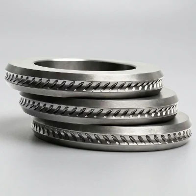
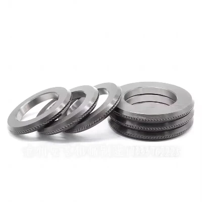
| Grooved Carbide Rolls | Groove geometry and roll dimensions |
| Carbide Nail Dies | Nail forming cavity and product geometry |
| Cold Heading Dies | Forming cavity and deformation requirements |
Manufacturing Process for Customized Dies
From Customer Drawing to Finished Tooling
Manufacturing Control Points
Focusing on critical control points that directly influence operating performance and wire surface quality.
| Manufacturing Stage | Main Control Point | Potential Impact |
|---|---|---|
| Material Selection | Carbide properties | Wear behavior |
| Blank Preparation | Basic dimensions | Tooling structure |
| Profile Machining | Working geometry | Product shape |
| Grinding | Dimensional accuracy | Finished dimensions |
| Surface Finishing | Working surface | Contact condition |
| Inspection | Dimensional verification | Specification compliance |
| Repair | Profile restoration | Tool reuse |
Manufacturing Evidence
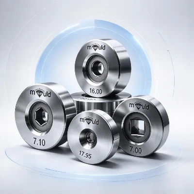
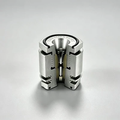
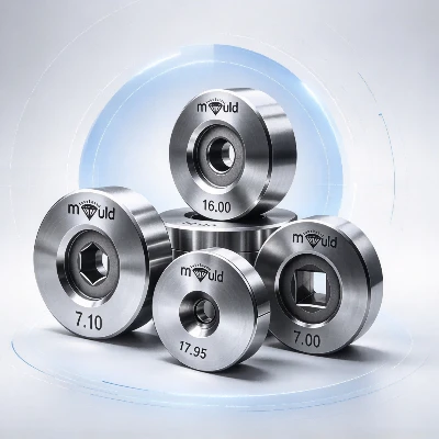
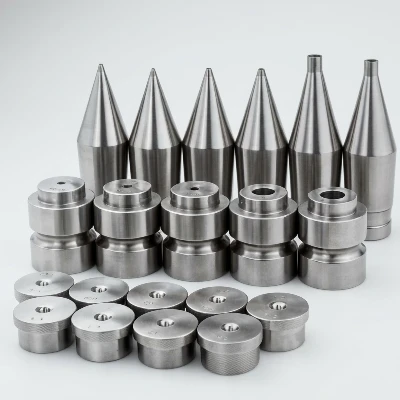
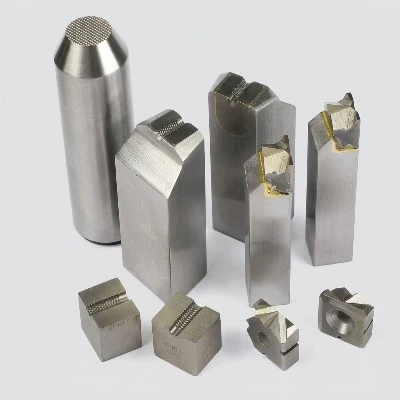
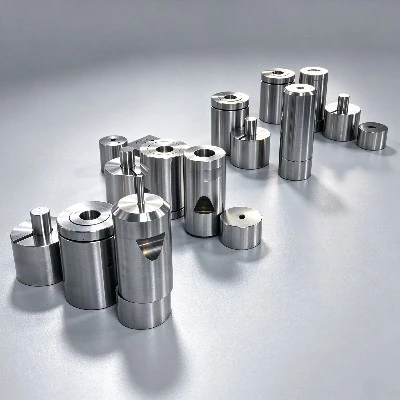
To demonstrate our manufacturing capabilities, production verification is supported by actual shop-floor documentation and photographs:
From Manufacturing Experience to Process Control
Our manufacturing experience since 1962 has been accumulated through the production of diverse carbide dies and metal-forming tooling. With a product range covering 30+ categories and more than 500 specifications, our production system adapts tooling structure and manufacturing controls directly to workpiece material, profile geometry, forming process, and equipment requirements.