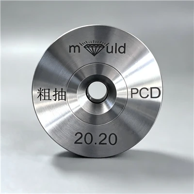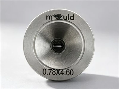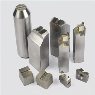

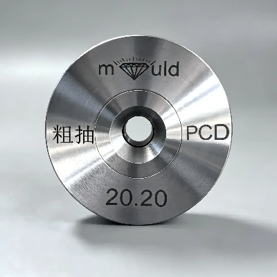
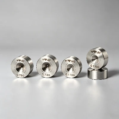
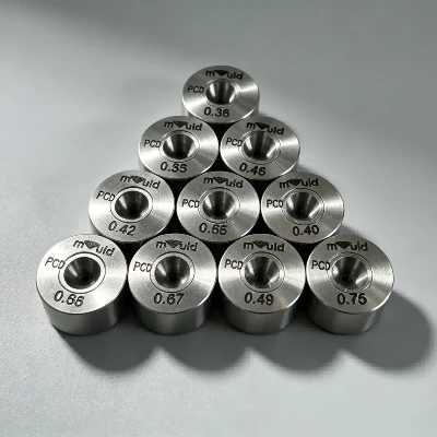
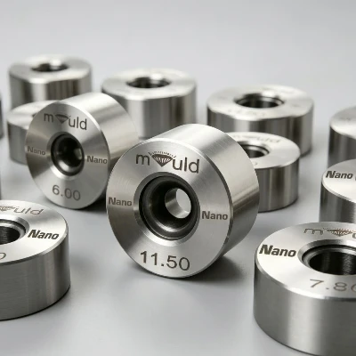
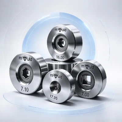
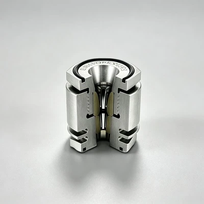
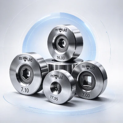
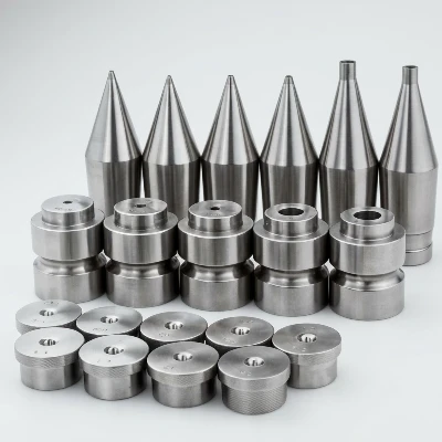
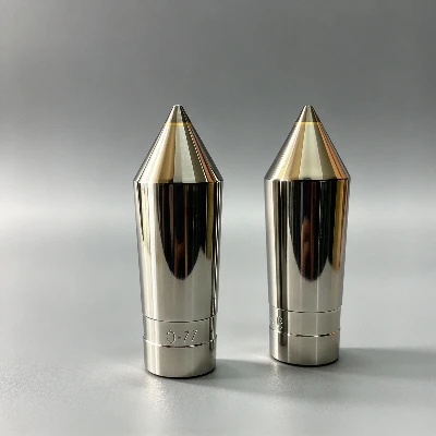
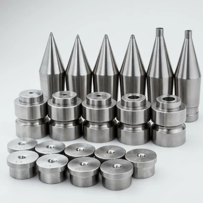
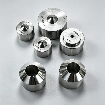
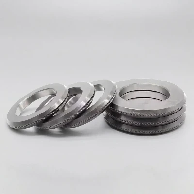
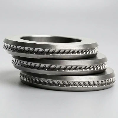

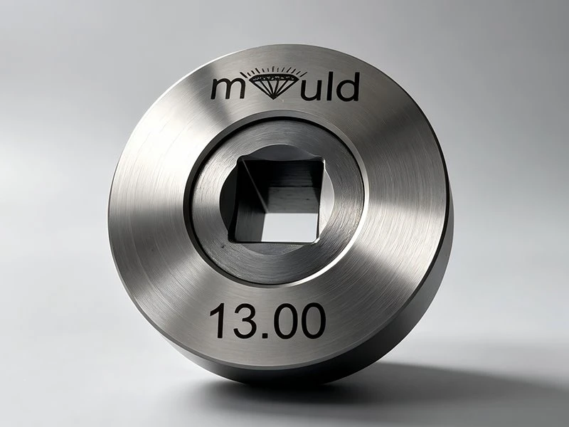
A tungsten carbide shaped wire drawing die is a forming tool with a specially machined carbide opening corresponding to the required wire profile.
The working opening normally consists of several functional zones:
Approach zone
Guides the incoming wire into the die.
Reduction zone
Progressively reduces the wire cross-section.
Bearing zone
Controls the final dimensions and profile.
Exit zone
Allows the drawn wire to leave the die with reduced friction and minimizes damage to the surface.
For shaped wire drawing, the geometry of the die opening determines the final cross-sectional shape. The die must maintain sufficient dimensional control while allowing the metal to flow plastically through the profile.
Typical profiles include:
|
Shaped Wire Profile |
Typical Description |
|
Square |
Four equal sides with controlled corner geometry |
|
Rectangular |
Two wider and two narrower sides |
|
Hexagonal |
Six-sided profile |
|
Oval |
Elliptical or oval-shaped section |
|
Flat |
Low-thickness rectangular section |
|
Trapezoidal |
Unequal parallel and inclined sides |
|
Special Profile |
Customer-specific cross-section |
|
Multi-Radius Profile |
Profile containing controlled radii and transitions |
How Does a Shaped Wire Drawing Die Work?
During drawing, the metal wire is pulled through the shaped carbide opening under tensile force.
The process can be simplified into four stages:
Wire preparation → Die entry → Cross-section reduction → Final profile sizing
As the wire passes through the reduction zone, compressive deformation occurs around the wire cross-section. The material flows toward the required profile while the bearing section establishes the final dimensions.
For example, when producing square wire, the die opening is not simply a round hole. Its four-sided geometry controls the width, height, corner radius, and dimensional tolerance of the finished wire.
The actual deformation depends on several parameters:
- Incoming wire dimensions
- Finished wire dimensions
- Cross-sectional area reduction
- Wire material and hardness
- Drawing speed
- Lubrication condition
- Die geometry
- Carbide grade
- Number of drawing passes
- Intermediate annealing requirements
For this reason, shaped dies should be designed according to the complete drawing process rather than only the nominal finished size.
Tungsten Carbide Material and Die
Construction
The working section is manufactured from cemented tungsten carbide, which is selected according to the wire material, drawing load, production volume, and required wear resistance.
A typical die construction consists of:
Tungsten Carbide Core
The carbide core provides the actual forming surface. Its grade can be selected according to hardness, toughness, wear conditions, and the material being drawn.
Common carbide compositions use WC-Co, where tungsten carbide provides hardness and cobalt acts as the metallic binder.
Shaped Working Profile
The profile is manufactured to the customer's required cross-sectional geometry. Critical dimensions include:
- Side length
- Width
- Height
- Corner radius
- Diagonal dimension
- Bearing length
- Profile orientation
- Transition geometry
Steel Die Case
For many industrial designs, the carbide insert is supported by a steel case. The case provides mechanical support and helps protect the carbide insert from external impact.
Polished Working Surface
The working surface must be finished sufficiently smooth to reduce friction and minimize surface defects on the drawn wire.
Why Use Tungsten Carbide for Shaped Wire Drawing?
Shaped wire drawing places different demands on the die compared with round wire drawing.
The die must withstand repeated contact with the wire while maintaining the geometry of the shaped opening.
Tungsten carbide is commonly selected because its mechanical properties are suitable for forming operations involving repeated abrasive and compressive loading.
The important selection factors are:
|
Factor |
Effect on Die Performance |
|
Carbide hardness |
Influences resistance to wear |
|
Carbide toughness |
Influences resistance to cracking and chipping |
|
Binder content |
Affects the balance between hardness and toughness |
|
Grain size |
Influences mechanical and wear characteristics |
|
Wire material |
Determines required carbide grade and geometry |
|
Drawing reduction |
Influences deformation load |
|
Drawing speed |
Influences heat generation and lubrication requirements |
|
Surface finish |
Influences friction and wire surface quality |
A harder carbide is not automatically the correct choice for every application. Excessive hardness without sufficient toughness can increase the risk of edge chipping, particularly when the shaped profile contains sharp corners or when drawing conditions generate unstable loads.
Shaped Wire Drawing Die Geometry
Die geometry is one of the most important factors affecting finished wire dimensions.
For a shaped die, the following parameters normally need to be defined before manufacturing:
Profile Dimension
The finished wire cross-section determines the basic die opening.
For example:
- Square: 5 × 5 mm
- Rectangle: 3 × 8 mm
- Hexagon: across-flat or across-corner dimension
- Flat wire: width × thickness
- Custom profile: CAD drawing or technical drawing
Corner Radius
Corner radius is particularly important for square and rectangular wire.
A controlled radius can reduce stress concentration and influence how the metal fills the profile during drawing.
Bearing Length
The bearing section controls the final dimensions of the drawn wire.
An excessively short bearing may provide insufficient dimensional control, while an excessively long bearing can increase friction and drawing force.
Reduction Zone
The reduction zone controls how the incoming wire transitions into the final profile.
For shaped wire, the transition must allow stable metal flow rather than forcing an abrupt change in cross-section.
Typical Materials That Can Be Drawn
Tungsten carbide shaped drawing dies can be engineered for different metal wire materials, including:
Carbon steel wire
Stainless steel wire
Spring steel wire
Copper wire
Brass wire
Aluminum wire
Nickel-based alloys
Other non-ferrous metal wires
The actual die specification should be determined according to the material's tensile strength, hardness, ductility, work-hardening behavior, and drawing reduction.
For example, stainless steel generally requires different drawing conditions from copper because the deformation resistance and work-hardening behavior are different.
Shaped Wire Drawing Die Manufacturing Process
A typical manufacturing workflow includes:
Technical drawing review → Carbide grade selection → Carbide blank preparation → Profile machining → Working geometry processing → Polishing → Dimensional inspection → Final inspection
For customized dies, the manufacturing process normally begins with the customer's wire profile drawing.
Important inspection items may include:
Profile dimensions
Corner radius
Bearing length
Die opening geometry
Surface roughness
Concentricity
Working-zone geometry
External dimensions
Carbide integrity
For high-precision applications, the finished die can be inspected against the customer's CAD profile or specified dimensional tolerances.
Customized Tungsten Carbide Shaped Wire Drawing Dies
Custom-shaped dies can be manufactured according to:
Wire cross-sectional drawing
CAD file
Finished wire dimensions
Die case dimensions
Drawing machine requirements
Wire material
Drawing process parameters
Required dimensional tolerance
For non-standard profiles, the customer's 2D drawing or 3D CAD file should be provided whenever possible.
This allows the die geometry to be evaluated before production and reduces the risk of producing a die based only on an incomplete product description.

FAQ
Q: What is a tungsten carbide shaped wire drawing die?
A: It is a wire drawing die with a non-round carbide working profile designed to reduce and form metal wire into square, rectangular, hexagonal, flat, oval, or customized cross-sections.
Q: What wire profiles can be produced?
A: Common profiles include square, rectangular, hexagonal, oval, flat, trapezoidal and customer-specific shapes. The actual profile depends on the die opening and drawing process.
Q: Can you manufacture custom shaped wire drawing dies?
A: Yes. Custom dies can be manufactured according to a 2D technical drawing, 3D CAD file, finished wire dimensions, or other dimensional specifications.
Q: What information should I provide when ordering?
A: At minimum, provide the wire material, incoming size, finished profile, finished dimensions, corner radius, required tolerance, drawing process and machine/die-holder dimensions. A technical drawing is preferred for non-standard profiles.
Q: Why is tungsten carbide used for shaped wire drawing?
A: Tungsten carbide provides a hard wear-resistant working surface while maintaining the dimensional stability required for repeated metal forming. The appropriate carbide grade still depends on the wire material and drawing conditions.
Hot Tags: tungsten carbide shaped wire drawing dies, China tungsten carbide shaped wire drawing dies manufacturers, suppliers, factory