

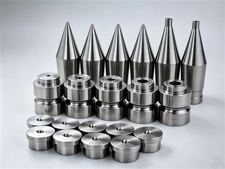
Wire Extrusion Tip Structure
The main areas of a wire extrusion tip include:
|
Component Area |
Function |
|
Tip Bore |
Guides the conductor |
|
Entry Section |
Allows the conductor to enter smoothly |
|
Working Section |
Maintains conductor positioning |
|
Exit Section |
Guides the conductor toward the extrusion die |
|
Tip Body |
Provides mechanical support |
|
Mounting Area |
Connects the tip with the extrusion tooling |
The internal bore is normally manufactured according to the conductor diameter and required process clearance.
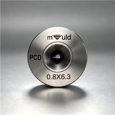
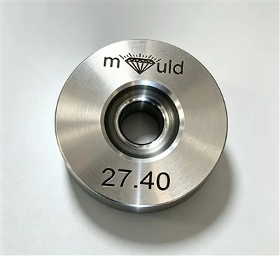
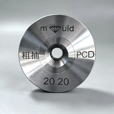
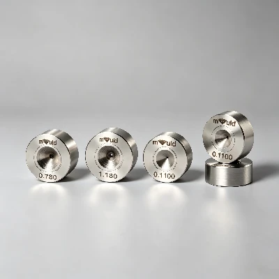
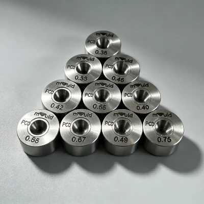
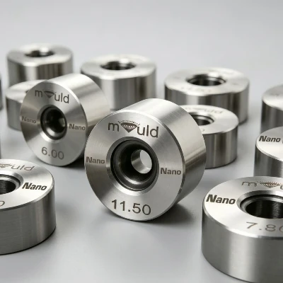
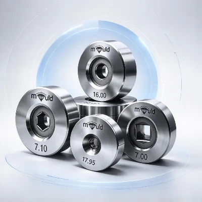
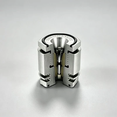
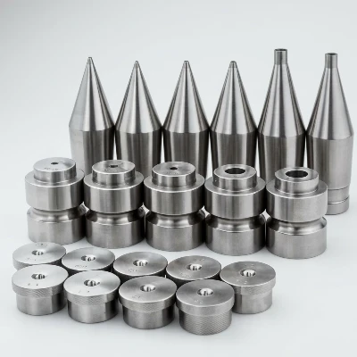
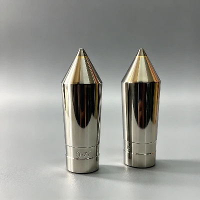
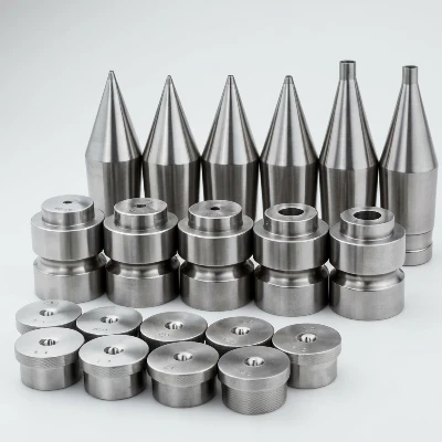
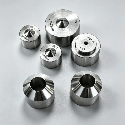
A wire extrusion tip is the inner tooling component located before or within the extrusion die assembly.
During extrusion, the conductor passes through the tip while molten insulation or coating material flows around it. The tip establishes the position of the conductor and provides the required clearance between the conductor and the surrounding extrusion material.
A typical extrusion tooling arrangement can be represented as:
Conductor → Extrusion Tip → Polymer Flow → Extrusion Die → Finished Insulated Wire
The tip and die must be designed as a matched tooling set to achieve stable coating thickness and concentricity.
Main Functions
Conductor Guidance
The internal bore guides the conductor through the extrusion head and helps maintain a consistent position.
01
Conductor Centering
Proper tip geometry helps control the position of the conductor inside the extrusion flow channel.
02
Material Flow Control
The relationship between the tip and die creates the flow passage for the insulation or coating material.
03
Insulation Thickness Control
The tip dimensions, die opening and extrusion conditions work together to determine the thickness of the material surrounding the conductor.
04
Surface Protection
A properly finished internal bore reduces unnecessary friction and potential damage to the conductor surface.
05
Materials
The material should be selected according to conductor material, extrusion temperature, production speed and expected wear.
Common materials include:
- Tool Steel
- Hardened Steel
- Tungsten Carbide
- Stainless Steel
- Other wear-resistant materials
For high-speed production or abrasive operating conditions, wear-resistant materials may be selected to maintain the bore geometry over longer production periods.
For copper and aluminum conductors, the working surface should also be properly finished to minimize conductor scratching or deformation.
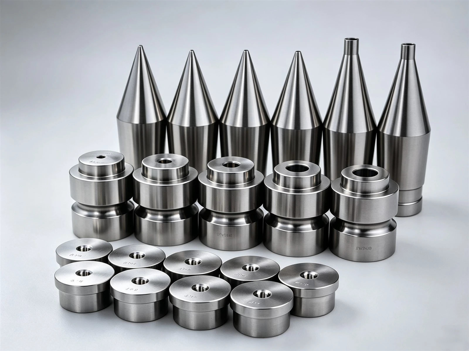

Wire Extrusion Tips for Different Conductors
Copper
Copper conductors require a controlled internal bore and smooth working surface because the conductor can be affected by excessive contact or an unsuitable bore finish.
Applications include:
- Power wires
- Control cables
- Automotive wires
- Building wires
- Electrical conductors
Aluminum
Aluminum is lighter and generally softer than copper, so tip bore geometry and surface condition are important for preventing unnecessary surface damage during extrusion.
Stranded Conductor Tips
For stranded conductors, the tip must accommodate the actual conductor construction rather than simply using the nominal cross-sectional area.
Important considerations include:
- Strand diameter
- Strand arrangement
- Conductor flexibility
- Compaction condition
- Finished insulation thickness
Wire Extrusion Tip Dimensions
The most important dimension is generally the tip bore diameter.
Other parameters include:
- Overall tip length
- Bore length
- Entry angle
- Exit geometry
- Outer diameter
- Mounting dimensions
- Concentricity
- Surface finish
For example, a customer specification may include:
Conductor: Ø2.00 mm copper wire
Tip Bore: Customer specification
Insulation: PVC
Finished Wire Diameter: 3.20 mm
Extrusion Line: Crosshead extrusion line
The final tip dimensions should be determined from the actual extrusion head and production parameters.
Applications
They are used in extrusion lines for:
Electrical wire
Power cable
Control cable
Automotive wire
Building wire
Communication cable
Data cable
Instrumentation cable
Industrial cable
Specialty insulated wire
They are particularly important in continuous extrusion processes where stable conductor positioning is required over long production runs.
Maintenance and Replacement
The tip should be inspected when wire dimensions become unstable or when extrusion quality changes.
Common signs of tip wear include:
Bore enlargement
Uneven bore wear
Conductor surface scratches
Changes in insulation concentricity
Unstable insulation thickness
Increased conductor movement
Polymer flow irregularities
The tip should be replaced when the bore geometry no longer meets the required process tolerance.
During maintenance, the tip should also be checked for polymer residue, mechanical damage and incorrect alignment.
FAQ
Q: What is a Wire Extrusion Tip?
A: A Wire Extrusion Tip is an inner extrusion-tooling component that guides and positions the conductor before the polymer insulation or coating is formed around it.
Q: What is the difference between a wire extrusion tip and a die?
A: The tip primarily controls the position and passage of the conductor, while the extrusion die controls the external shape and dimensions of the polymer coating.
Q: Can Wire Extrusion Tips be customized?
A: Yes. Tips can be manufactured according to conductor diameter, conductor construction, extrusion-head dimensions and production requirements.
Q: What materials can be used for extrusion tips?
A: Tool steel, hardened steel, tungsten carbide and other wear-resistant materials can be selected depending on the conductor and extrusion conditions.
Q: Can one extrusion tip be used for different wire sizes?
A: Normally, the tip bore must correspond to the conductor size and process requirements. Different conductor diameters generally require different tip specifications.
Hot Tags: wire extrusion tips, China wire extrusion tips manufacturers, suppliers, factory