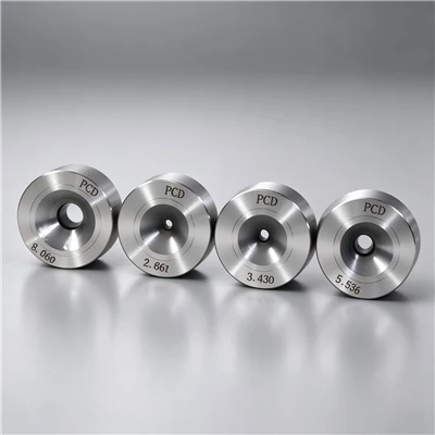

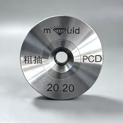
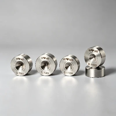
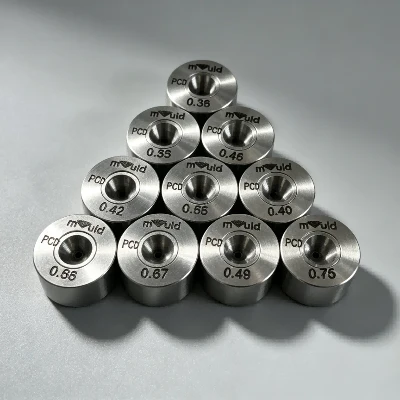

Wire drawing is often described as a straightforward reduction process: a metal rod or wire is pulled through a die to produce a smaller cross-section. In practice, the deformation is more complex. Metal must change direction as it enters the reduction zone, flow under pressure along the die surface, and leave through a calibrated opening. The tooling profile therefore affects not only the final diameter, but also drawing force, friction, temperature, residual stress and the risk of defects.
For manufacturers working with steel, stainless steel, copper, aluminum and other ductile metals, understanding this relationship is important when selecting tooling and setting process parameters. Wire Drawing Dies are not simply tools for reducing wire diameter. Their internal profiles interact with material properties, area reduction, lubrication, drawing speed and the condition of the incoming rod. A design that performs well in one application may not deliver the same result under different operating conditions.
The Main Zones Inside a Drawing Die
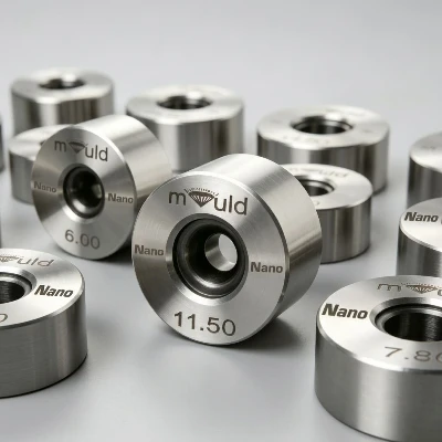
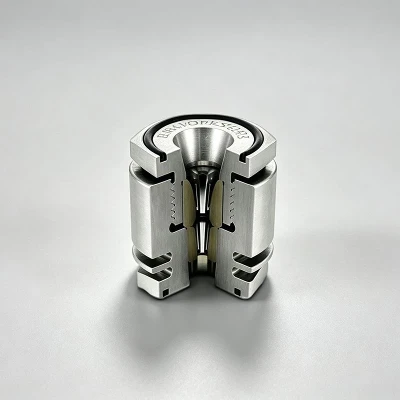
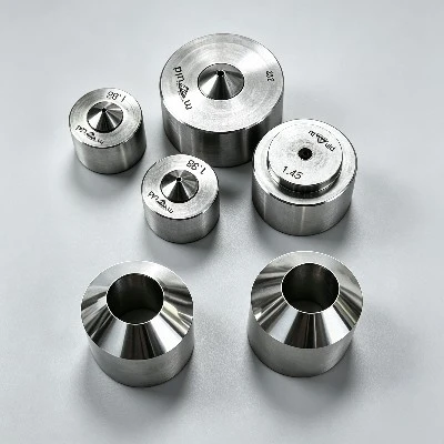
A conventional wire drawing die generally contains an entry zone, an approach or reduction zone, a bearing zone and a relief zone. Each section has a specific function in controlling the movement of metal through the tooling.
- Entry Zone: Guides the incoming wire and helps introduce lubricant into the working area.
- Approach Zone: Reduces the cross-sectional area by forcing the metal to flow inward under compressive pressure.
- Bearing Zone: Also called the calibration zone, it controls the final diameter and helps establish dimensional consistency.
- Exit Relief Zone: Reduces contact as the finished wire leaves the die.
The reduction and bearing sections have particularly strong effects on deformation and contact conditions. In the approach zone, the metal changes direction while its cross-section decreases. In the bearing zone, most of the intended area reduction has already occurred, and the wire passes through a section of controlled diameter while remaining in contact with the die.
The transitions between these regions also matter. Abrupt changes in profile can disturb metal flow and increase local stress. A continuous, accurately finished contour helps the material move through the tooling more consistently.
Approach Angle and the Shape of Metal Flow
The approach angle determines how quickly the wire is reduced over the length of the deformation zone. A relatively large angle creates a shorter contact path, but it forces the metal to change direction more sharply. This can increase redundant deformation: plastic work that does not directly contribute to the required reduction in cross-sectional area. Higher redundant deformation may create a less uniform strain distribution between the surface and the center of the wire.
A smaller angle gives the metal a more gradual path through the reduction zone. It can reduce abrupt flow changes, but it also lengthens the contact area. The longer interface may increase frictional work and heat generation, particularly if lubrication is inadequate or the drawing conditions are demanding.
There is no universally optimal approach angle. The suitable value depends on several operating factors:
- Incoming and final wire diameters.
- Reduction ratio per drawing pass.
- Material strength and ductility.
- Drawing speed and lubrication conditions.
- Required dimensional accuracy and surface quality.
Research on steel and copper drawing has shown that angle changes can affect drawing force and radial stress differently at the surface and center. The correct design is therefore a balance between deformation efficiency and interface friction, rather than simply choosing the smallest or largest possible angle.
Bearing Length and Final Wire Quality
The bearing zone provides the final sizing section. Its diameter establishes the target wire size, while its length influences how long the wire remains in contact with the die after the main reduction has taken place. This contact helps stabilize diameter and roundness, but it also produces friction.
If the bearing is too short for the application, the wire may not receive sufficient calibration. Dimensional variation, loss of roundness or unstable sizing can result, especially when upstream conditions fluctuate.
On the other hand, an excessively long bearing increases the contact area between the wire and tooling. This can raise friction, drawing force and temperature. It may also accelerate wear or make lubrication more difficult to maintain along the interface.
Different bearing contours can also alter radial stress distribution. A modified profile may reduce surface radial stress under particular conditions while changing stress at the wire center. This illustrates why bearing length and shape should be evaluated together with material behavior and friction, rather than treated as dimensions that can be selected independently.
How Die Design Affects Force, Friction and Heat
The drawing force is the combined result of several contributions. One part is the work required for the intended reduction in area. Another is redundant deformation caused by changes in the direction and distribution of metal flow. A further contribution comes from friction at the wire–die interface.
The approach profile affects the balance between useful and redundant deformation. The bearing profile and contact length influence frictional work. Die diameter, approach angle and bearing length are therefore important geometric variables in drawing-force analysis. However, their effects cannot be separated from the coefficient of friction, material flow stress, reduction ratio and drawing speed.
Friction converts mechanical work into heat at the contact surface. Higher interface temperature can affect lubricant performance, surface condition and tooling wear. At higher drawing speeds, the balance between lubricant-film formation, friction and heat removal can change. A profile that reduces force in one operating window may not provide the same benefit when speed, lubricant or material changes.
For process engineers, force and temperature trends are useful diagnostic signals. A gradual increase in drawing force may indicate die wear, lubrication deterioration, material variation or a mismatch between the selected profile and process conditions. Measurements should be interpreted alongside wire dimensions, surface inspection and tooling condition.
Defects Linked to Uneven Deformation
Poorly matched tooling can contribute to several types of wire defects. Excessive surface strain or friction may lead to scoring, scratches, surface roughness and accelerated wear. Uneven deformation across the wire section can produce non-uniform residual stresses. Depending on material quality, reduction and process settings, internal tensile stresses may contribute to center cracking or chevron-type defects.
Dimensional problems can also emerge when the bearing zone is worn, damaged or incorrectly sized. A wire may leave the die with an inconsistent diameter, ovality or surface finish. In multi-pass drawing, these variations can carry forward and complicate later reductions.
However, not every defect originates from tooling design. Other possible contributing factors include:
- Inclusions and pre-existing defects in the incoming rod.
- Unsuitable material heat treatment.
- Excessive reduction per pass.
- Poor surface cleaning before drawing.
- Inadequate lubrication or unstable process conditions.
Effective troubleshooting compares the defect location and pattern with the die condition, material batch, process records and operating parameters. This helps distinguish tooling-related problems from material or process issues.
Selecting a Profile for the Actual Drawing Operation
Tooling selection should be based on material properties and production requirements, including incoming and target diameters, reduction per pass, dimensional tolerances, drawing speed and lubrication conditions. These factors help determine the appropriate approach angle, bearing length and overall die profile.
The complete die profile should also be evaluated for smooth metal flow, stable sizing and consistent contact. Surface finish, concentricity and manufacturing accuracy are important for controlling friction and preventing uneven deformation.
For demanding applications, finite-element analysis and production trials can help compare different profiles. Simulation provides insights into strain distribution, radial stress and contact pressure, while actual drawing tests verify performance under operating conditions.
A practical selection process should consider the following factors:
|
Selection Factor |
Key Considerations |
Purpose in Die Selection |
|---|---|---|
|
Material Compatibility |
Metal strength, ductility and wear characteristics; tooling material compatibility |
Ensures the die suits the material being drawn |
|
Reduction Requirements |
Initial and target diameters, cross-sectional reduction per pass and drawing sequence |
Helps determine a suitable approach profile |
|
Dimensional Control |
Bearing diameter, bearing length, contour and required wire tolerance |
Maintains dimensional accuracy and consistency |
|
Surface Quality |
Die surface finish, contact conditions and lubrication |
Reduces unnecessary friction and potential surface defects |
|
Production Conditions |
Drawing speed, equipment limitations, cooling and lubricant performance |
Ensures the selected profile matches actual operating conditions |
These factors should be evaluated together rather than independently. Changes in reduction ratio, drawing speed or lubrication may require adjustments to the die profile. Final selection should be validated under actual production conditions to confirm dimensional accuracy, surface quality and operating stability.
A Process-Based Approach to Die Design
The relationship between tooling profile and metal flow is a system issue. A suitable design promotes controlled deformation, stable sizing and manageable friction across the full operating range. It should be selected with the wire material, reduction schedule, lubrication and drawing equipment considered together.
Manufacturers can improve production consistency by monitoring several key indicators:
- Drawing Force: Identify changes in deformation resistance and friction.
- Wire Diameter: Check dimensional stability throughout production.
- Surface Quality: Detect scratches, scoring and other drawing defects.
- Die Wear: Evaluate whether tooling condition is affecting product quality.
When process conditions change, the tooling should be reassessed rather than assuming that an existing profile remains optimal. Well-designed Wire Drawing Dies support efficient metal flow, but reliable results ultimately depend on coordinating tooling design with material preparation, lubrication and process control.
Mouldzy Supports Customized Tungsten Carbide Tooling
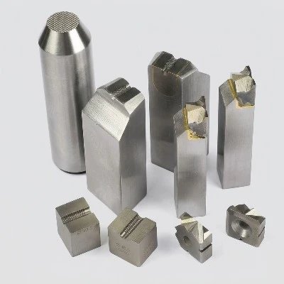
Hejian Strains Of Hard Alloy Mould Co., Ltd. is a manufacturer specializing in tungsten carbide dies and industrial tooling. Its product range includes shaped wire dies, extrusion tips and dies, shaving dies, grooved carbide rolls, carbide nail dies and cold heading dies, as well as PCD and diamond tooling.
Key Manufacturing Capabilities:
- Product Customization: Tooling development based on customer drawings, samples and existing specifications.
- Precision Manufacturing: Material selection and precision machining for different tooling requirements.
- Product Development: Support for new tooling, replacement dies and non-standard applications.
- Application Support: Technical assistance in matching tooling specifications to production conditions.
With extensive manufacturing experience and application-focused customization, Mouldzy provides customized Wire Drawing Dies and other industrial tooling to meet the specific production requirements of wire manufacturers and industrial buyers.